PiStep2 Quad Stepper Motor Control Board for Raspberry Pi
Quad Stepper Motor Control Board for Raspberry Pi
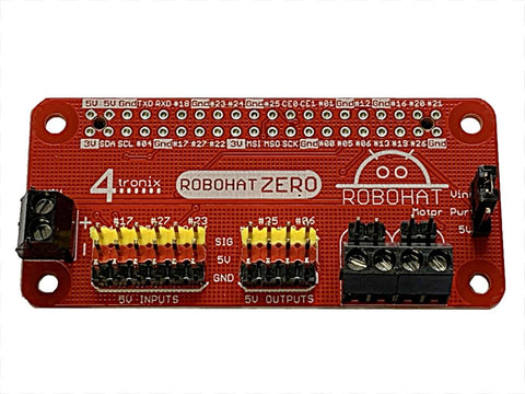
Fully Assembled - No Soldering Required
Works with UniPolar (5-pin) stepper motors. Not with Bipolar (4-pin) motors.
Stepper motors (optional extra) and Raspberry Pi not included
Also available in Dual (2 steppers) version
** NB the Raspberry Pi Model 3B+ has a POE connector which collides with one of the motor connectors on this board. For that reason, we now include an extension header with every unit which allows the PisTep2 to sit further from the Pi.
Various Power Options
- Powered from the Raspberry Pi 5V
- From the 2-pin Terminal (whatever voltage is required for the motors)
- Micro-USB - 5V only
Pinout is simple:
- Physical pins 11, 12, 13, 15 for Motor A (GPIO 17, 18, 27, 22)
- Physical pins 16, 18, 22, 7 for Motor B (GPIO 23, 24, 25, 04)
- Physical pins 33, 32, 31, 29 for Motor C (GPIO 13,12,6,5)
- Physical Pins 38, 37, 36, 35 for Motor D (GPIO 20,26,16,19)
Each pin has an associated white LED so you can see the stepper signals going through
Power Supply Alternatives
-
Jumper VCC-VSTP (default). Power from the motors is taken from the Raspberry Pi 5V line
- Micro-USB into Raspberry Pi. 5V for the Pi and the stepper motors goes through a poly-fuse which can trip if 2 motors are used simultaneously
- Micro-USB into the PiStep board. 5V for both the Pi and the stepper motors is provided directly from the 5V USB input so no problems with 2 motors at once
- Jumper VSTP-VIN. Power for the motors is provided from the 2-pin screw terminal, so can be any voltage that the steppers can handle. Ensure you use the correct polarity! We recommend to keep it below 12V. You will find that the stepper motors can go up to 9V and will be able to step faster, the higher the voltage that is applied, but there will be some deterioration of the life of the stepper motor at a higher voltage.
Python Programming
Please see the excellent example here for some pointers. You will need to change the pin numbers as above and also change the speed so it steps at a visible rate. You may also want to remove the print statements to speed it up. The lines in Red below are changed from the original to operate Motor A.
# Use BCM GPIO references
# instead of physical pin numbers
GPIO.setmode(GPIO.BCM)
# Define GPIO signals to use
# Pins 18,22,24,26
# GPIO24,GPIO25,GPIO8,GPIO7
StepPins = [17,18,27,22]
# Set all pins as output
for pin in StepPins:
print "Setup pins"
GPIO.setup(pin,GPIO.OUT)
GPIO.output(pin, False)
# Define some settings
StepCounter = 0
WaitTime = 0.01
ScratchGPIO Programming
 Set motor type for Scratch to be Stepper motor
 Set the position of the stepper motor A
 Set the speed of the stepper motor A


